NYX-101 Guiding Recommendations
About Strain wave gearing
Harmonic reducers are innovative gearboxes utilizing the strain-wave principle. They feature a dynamic mechanism where a flexible toothed inner ring rotates around an oval-shaped drive shaft within an outer toothed ring. This unique design exploits the difference in tooth count between the inner and outer rings to create relative motion.
Compared to conventional gearing systems like worm gears, harmonic reducers offer a host of advantages. These include a remarkable capacity for high torque, exceptional precision and repeatability in positioning, a compact and space-efficient construction, zero backlash for precise motion control, impressive single-stage reduction ratios, and a remarkable level of torsion stiffness.
At Pegasus Astro, we’ve harnessed the potential of strain wave gearing reduction, incorporating belt-driven mechanisms in both axes. This system is renowned for its minimal period errors and robust torque output. Achieving a guiding accuracy as low as 0.5 arcseconds, typically ranging between 0.4 to 0.8 arcseconds, is now attainable.
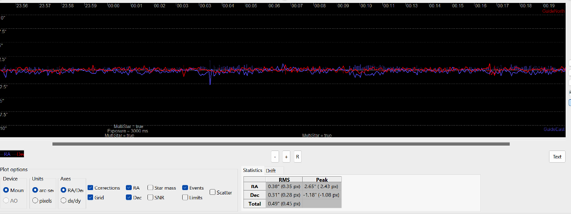
Our in-depth analysis reveals a distinct pattern in the periodic behavior of the strain wave gear. It starts with a heightened periodic error offset during the initial two minutes, followed by a remarkably stable tracking performance over the next three minutes. The cycle concludes with another spike in periodic error during the final two minutes. In total, this periodic cycle spans 7.16 minutes or 430 seconds. Our gear systems exhibit a measured periodic error of ±20 arcseconds or less, underscoring their reliability and precision.
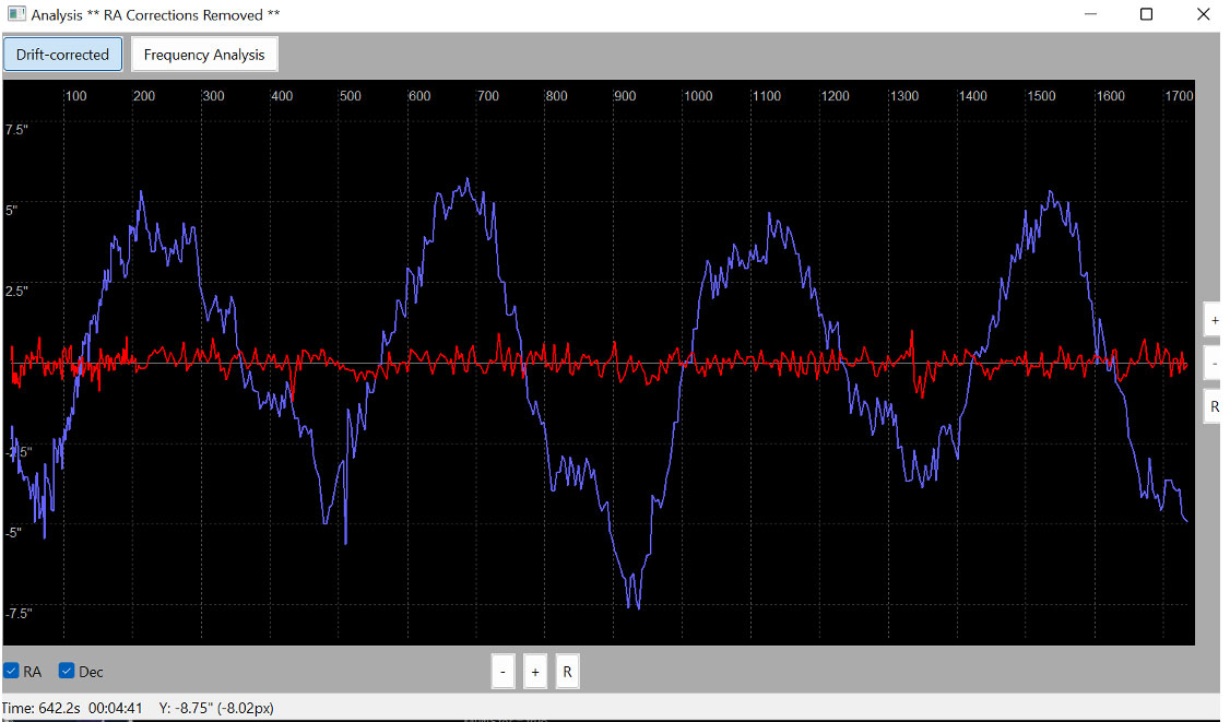
Strain wave gears exhibit distinctive periodic error characteristics that set them apart from traditional worm gears. Notably, strain wave gears display variability in periodic error magnitude depending on the telescope’s load and the direction of movement. This inherent variability poses a challenge when attempting to apply a uniform periodic error profile to these gears.
Nevertheless, due to the repeatability of the periodic error under consistent loads, we have developed a solution that enables the guiding system to adapt and compensate for this inherent variability. This solution, referred to as “Predictive PEC” (Periodic Error Correction), is designed to address these challenges and enhance the tracking performance of telescopes equipped with strain wave gears.
In our tests, we used PHD2 (v2.6.11) software.
PHD2 1st time setup guide
- Start by selecting the New Profile Wizard.
- Select your guide camera from the drop-down list. Prefer the native driver over the ASCOM if you have the option.
- Set Binning level to 1×1
- Choose the highest available bit depth
- Set the focal length of your guidescope or the focal length of your telescope if you use an OAG
- Select the PegasusAstro NYX (ASCOM)
- Select the Pegasus Astro Falcon rotator if you use one
- Name your profile
- Built a dark library (Don’t miss this step)
Click on the PHD “brain” icon to open Advanced Settings,
Camera tab settings
- Set Saturation by Max-ADU value to 255 if you use an 8 bit camera or to 65535 if you use a 16 bit one
- Set Gain 40-60% (depends on camera).
Guiding tab settings
- Increase Search region (pixels) to 30
- Enable Reverse DEC output after meridian flip
- Disable Stop guiding when mount slews
- Use Multi-Star Guiding: It’s advisable to utilize a multi-star guiding system. This approach enhances guiding accuracy by referencing multiple guide stars, ensuring more stable tracking performance. We aim to help phd2 determine the best centroid and have multiple stars available (9-12) to guide using multi-star to compensate for seeing.
Check Recommended Guiding Camera Settings:
- Prefer the native driver over the ASCOM if you have the option.
- Set Gain 40-60% (depends on camera).
- Use Bin 1×1
- Use Highest bit depth available (12 to 16)
- Star profile must have a peak. Try to focus on the guiding star as good as you can.
Mount guide Algorithms
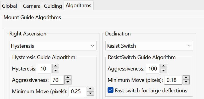
The most common approach for mount guiding is to use the Hysteresis algorithm for the Right Ascension (RA) axis and the Resist Switch algorithm for the Declination (DEC) axis. These algorithms help to minimize guiding errors and enhance tracking precision.
By following these recommendations, you can optimize your telescope guiding for improved tracking performance and high-quality astrophotography results.
The common mount guiding approach is to use the Hysteresis algorithm for Right Ascension and Resist Switch for the Declination axis.
PHD2 Predictive PEC Guide Algorithm (PPEC)
The PPEC algorithm is different from the others in PHD2 because of its modeling and predictive capabilities. The algorithm analyzes the tracking performance of the mount in real time and once that analysis is complete, it will compute guiding corrections even before a repetitive error is actually seen.
Issuing proactive guiding corrections reduces the time delay inherent in traditional guiding and can significantly improve performance. With the other algorithms, which are completely reactive, guide corrections are issued only after the error has been seen on the camera sensor.
Once guiding has begun, the algorithm analyzes the performance of the mount and looks for tracking errors that are repetitive and thus predictable.
Since PPEC employs a learning process, it will usually take about 2 worm periods to model the mount and become fully effective. During this training period, the algorithm will behave more like the ‘hysteresis’ algorithm, so you won’t normally see a performance penalty while the internal model is being built. Instead, you’re likely to see a steady improvement in tracking as the model is refined and the algorithm shifts seamlessly from hysteresis to predictive mode. This improvement can usually be seen even before the medium-term mount behavior is fully modeled.
Since the PPEC model is implicitly tied to the state of the gear train, it must be re-learned if the mount is slewed by a substantial distance. For the same reason, it can’t be retained across different guiding sessions, which is why conventional PEC is important. However, the PPEC model will remain intact during dither operations and while guiding is paused (via automation) for activities like focusing. For the most common use case, namely imaging the same target for multiple hours with periodic dithering, the PPEC model will remain valid. In any case, the learning process and transition from one mode to the other is handled automatically, so you won’t need to pay it any attention.
The ‘predictive gain’ and ‘reactive gain’ parameters are exposed in the Advanced Settings dialog, and their default values for these parameters should work well for most mounts. You should be conservative about changing them because bad choices for these parameters can definitely make your guiding worse.
During the training period, the algorithm needs to identify periodic errors in the observed guide star movement. For initial trials, you can use the worm period of your mount as the starting point for the ‘period length’. This gives the algorithm a good starting point, but you should also leave the ‘auto-adjust period’ option checked. This tells the algorithm to adjust the period as needed to better control whatever periodic errors it finds. Once you have run the algorithm multiple times and are happy with the results, you can leave this field set to whatever value was computed in the previous sessions.
The ‘Retain model (% period)’ parameter specifies how long the mount can track unguided before the PPEC algorithm will be reset. This is computed as a percentage of the current period length. This is useful in situations such as auto focusing where the mount is continuing to track at the sidereal rate but guiding isn’t being done. It also applies to westward changes in the RA pointing position from slewing.
Care must be taken if the default setting of 40% is adjusted upward. Running for extended periods of time unguided causes the PPEC model to lose accuracy, in which case a reset would be the best course of action. The point where that occurs is specific to the mount and the current seeing conditions, so you may need to experiment if you want to adjust this parameter.
By following these settings and recommendations, you can fine-tune your guiding system to optimize the tracking performance of your telescope for astrophotography, particularly on the Right Ascension axis.
Improve guide results of NYX-101 mount with PPEC
Predictive PEC (PPEC) Quick Guide:
To optimize your guiding system with Predictive Periodic Error Correction (PPEC) on the Right Ascension (RA) axis, follow these settings and guidelines:
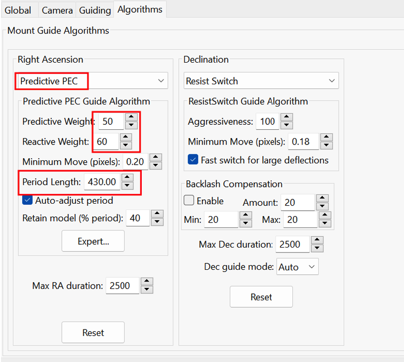
- Enable Predictive PEC for RA Axis: Activate Predictive PEC specifically for the Right Ascension axis.
- Use Default Predictive and Reactive Weights: Keep the Predictive Weight and Reactive Weight at their default values. These values have been tested and proven effective. Increasing these weights can lead to overcorrection, resulting in higher tracking errors.
- Set the Period Length to 430 with Auto-Adjust: Configure the period length to 430 and ensure that the “auto-adjust period” option is checked. This setting allows the algorithm to automatically adapt and fine-tune the period based on the measured guiding PE cycle.
- Guiding Exposure Duration: Set your guiding exposure duration to 1 second. This is the time interval during which the guiding system analyzes the star’s movement and applies corrections.
- Observe Guiding for 1-2 Cycles: Allow the guiding system to run for 1-2 cycles, which is approximately 7 minutes per cycle. You should notice an improvement in guiding accuracy after the first cycle, and this improvement will gradually become more pronounced as time progresses.
- Changing Imaging Targets: If you switch to a different imaging target, be aware that the PPEC model will re-initiate its learning curve for the new target. This is important to maintain accurate guiding.
- Consider Seeing Conditions: In cases of poor seeing conditions, based on your tests, PPEC may not provide a significant advantage over the Hysteresis algorithm. In such situations, it might be more practical to rely on Hysteresis for guiding, as PPEC’s benefits may not be fully realized under challenging seeing conditions
By following these settings and recommendations, you can fine-tune your guiding system to optimize the tracking performance of your telescope for astrophotography, particularly on the Right Ascension axis.
Guiding Under the stars best practice guide
Polar Alignment: Ensure that your polar alignment is as accurate as possible. Aim for an error of less than 30 arcseconds in your polar alignment. If you suspect a significant polar alignment error, you can temporarily disable guiding in the Declination (DEC) axis and monitor the DEC curve on the graph. A significant and rapid offset in one direction from the zero axis could indicate a polar alignment issue.
If you suspect that your polar alignment is way off, try to turn off DEC axis guiding and monitor the DEC curve in the graph if it quickly offsets in one direction from the zero axis.
Although using Guiding assistant is a good proven practice, in harmonic mounts it tends to suggest higher minmo settings (2 to 3 times higher than the ideal value) due to periodic error. Try lower values (1/2 to 1/3 than the suggested) and watch if your guiding has improved.
Looping: Adjust your guiding interval based on the prevailing seeing conditions. In general, a guiding interval of 1.0 second is a good starting point. You can consider using a shorter interval of 0.5 seconds when the seeing conditions are favorable. However, during poor seeing conditions, using a shorter interval might cause the guiding system to overcorrect, resulting in high Half-Flux Radius (HFR) values and producing blurry images. In such situations, consider extending the guiding interval to a range of 1.5 to 3 seconds but during the first 14 minutes when the PEC curve is being calculated, you should choose 1.0 second guiding exposures. After that period, choosing higher guiding intervals depends on the load the setup and the seeing.
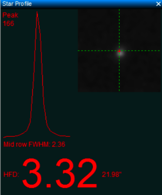
Focusing: Let PHD2 to choose a suitable star by pressing the Auto-select star icon and use the star-profile tool to confirm focus and shape – you want a pointed top. Try to focus the guiding star as good as you can.
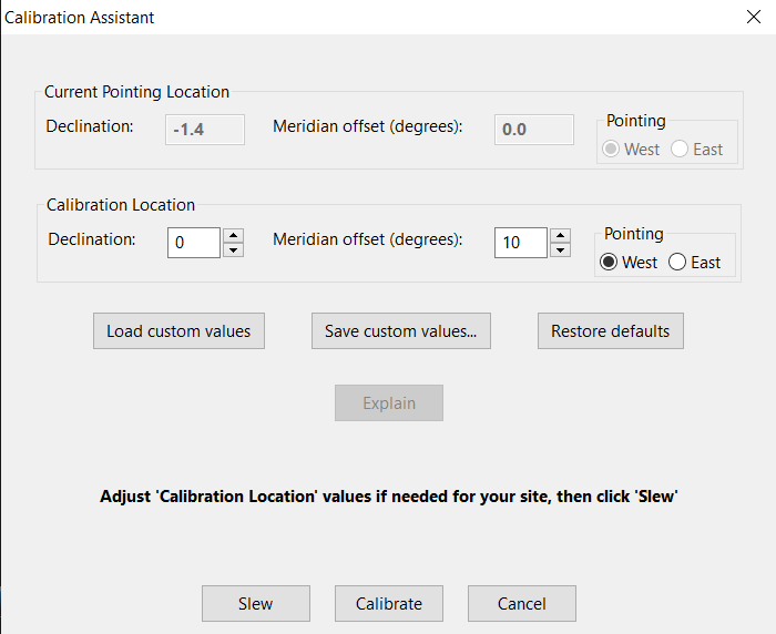
Calibration: Slew the mount to a region within 1 hour of the local meridian and within +- 20 degrees of celestial equator. You can also use phd2 Calibration assistant tool. If you fail to achieve a good calibration, try reducing the exposure to 0.5 secs and repeat the process.
Guiding Assistant: When calibration is finished close the calibration tool, leave the mount at the same spot and run guiding assistant for at least two minutes. Don’t measure backlash. Apply the suggested minMo settings as a starting point.
Guiding Improvement: In general, the default PPEC settings work very well regardless of the telescope used and don’t need further improvement. PHD2 guiding assistant tends to underestimate the minMo values in harmonic mounts due to the periodic error. Observe the guiding RMS values after the PPEC curve has been applied and lower the recommended minMo values.
Guidescope vs OAG: Use astronomy tools Guidescope suitability calculator to measure the imaging guiding ratio https://astronomy.tools/calculators/guidescope_suitability
A ratio of 1:1 is preferred, while the maximum acceptable is 1:3. In harmonic mounts due to the lack of backlash and periodic error being the determining factor, we aim for continuous short pulses, as opposed to worm gear mounts, where the goal is an infrequent and soft reacting mount. When using an OAG, we can achieve lower pixel scale guiding values which are ideal for harmonic mounts that can very fast and accurately follow short pulses leading to sub half arcsecond RMS when seeing is also favorable.
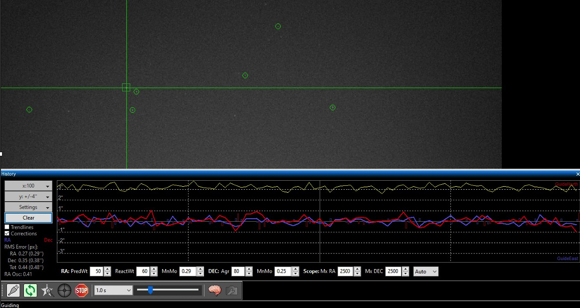
By following the above guiding recommendations, we achieved a tracking error of 0.3’’ in RA by using the Predictive PEC algorithm in PHD2.
- Mount = NYX101 (ASCOM), connected, guiding enabled, xAngle = -179.3, xRate = 2.840, yAngle = 89.9, yRate = 6.264, parity = +/+
- Norm rates RA = 7.5″/s @ dec 0, Dec = 6.8″/s; ortho.err. = 0.7 deg
- X guide algorithm = Predictive PEC, Control gain = 0.600
- Prediction gain = 0.500
- Minimum move = 0.290
- Pixel scale = 1.09 arc-sec/px, Binning = 1, Focal length = 550 mm
- Telescope: SW Esprit 100
- Guiding: OAG
For more information about Predictive PEC (PPEC):

